Monday, 25 October 2010

4.0 Nose Model

The next stage of the model was to shape the nose and add the nostrils. I first needed to select the inner nose edges and then drag them using the shift key, which copied the polygon. This started to create the nostrils but because I didn't anticipate the amount of splines I would need, I had to cut new lines and create new vertices's to give the nose shape.


There was also problems with the flow of the lines because they didn't compliment the structure a nose I was finding it very hard to make the model flow without having lots of triangular shapes in it.

After alot of 'cutting' and 'welding' I had made a flat mask of the nostrils. I then went into the left view and dragged some of the vert's out to give the nostrils some depth. The last part was to create two new polygons where the gaps for the nostrils were. Here I used the extrude tool to take the nostril cavity into the head.

Overall I was quite pleased with the nose because it was proving to be quite difficult to get the lines right, and I never thought I was going to get there. If I knew the problems I was going to encounter, I would of changed my original topology design drawings. The nose wasn't one hundred percent perfect but I will probably try and shape it better later.

Friday, 22 October 2010

3.0 Face Model

Once the initial face mask was made I next needed to use the side photo to extend the vertices's out to match the photo. I started by selecting the verts in a line down the center of the face on the front view and then dragging them to the right on the left view.

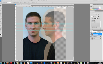
Here I had to use my judgment to place all the verts in the right places, I used the front view as a guide to see how close the verts should be to each other. In the more busy parts of the model I selected one vert at a time from the front and placed them in the right position using the left view.
Once this was done I selected all the verts down the center of the face and in 'Edit geometry' I clicked on the 'Maker planer' button and hit the x. This aligned all the verts up into a straight line. I then used a Symmetry Modifier to create the other side of the face. I had to flip the image and then align it (using the gizmo) so it matched up which my original model. Bellow is how the face looked.

The whole face gave me a better perspective of what I had done and I could now start to move the vertices's about abit to shape the face better. Trying to make the line flow from one side of the face was important to make the shape look real.


Wednesday, 20 October 2010

2.0 Reference Plates/Splines

Once the Topology was complete I opened up 3ds max and created a plane object. Next I needed to open up the material editor and import my PSD file that I had produced. I then added a UVW Map modifier to the plane, this made the photo retain it's original aspect ratio. I then clicked on Bitmap Fit which brought back the dimensions and it could also be adjusted to fit the plane. I also bumped the self illumination in the material editor up to 100 so the photo could seen at any angle.


I then needed to create another plane but with the side view of my face. I did this by coping the first plane and rotating it around to the correct position. The view ports were then set up to show the just the left and front views, as these were the only ones I would be using.

Now I needed to start the modeling process. I started with the Line tool to connect all of the quads of the Topology by making building up small quad shapes that would cover my whole face and make a mesh to work with. I used the snap tool with vertex checked to make this process simpler to complete.

Once the whole face was complete I selected one line shape and converted it to an editable poly. Here I used the attach tool to connect all the splines together to make one line object. I also used the Weld tool to reduce the amount of vertices's that were used in the model. This would over half the amount of verts thus making it less likely to make a mistake later on.


Tuesday, 19 October 2010

1.0 Topology

The first part of the project was to produce the Topology. I needed to take two photos of myself from the front and also from the side view. Special care was taken to try and keep the distance of both photos the same from the camera. This would be important because resizing the photo after would cause a lot of problems. These photos would be used as references for my model.
The next step was to load the pictures into photoshop. Here I lined the pictures so the facial features were in line with each other. To do this I used the ruler lines as guides to help me line them up perfectly.

I now had to start to build up the edges on my face. I choose a blue coloured brush and started to define the face by drawing over lines, wrinkles or protrusions. Here I was isolating all the key areas. The last part was to draw in to inner Topology. This was done be using a smaller red coloured brush to join all the blue Topology lines up. This made lots of small quads that would build up the contours of the face. The use of quads was important because triangles would cause a pinching effect when the modeling begun. I found this quite difficult to totally eliminate every three sided shape but I tyred to minimise them and try not have any in key areas.